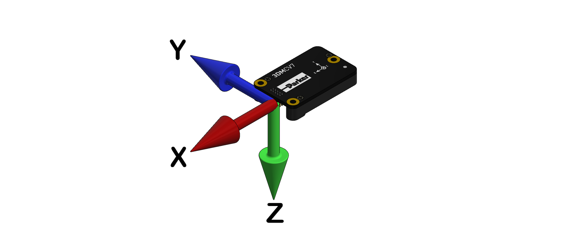
Sensor Frame
The sensor frame is indicated on the top of the device and shown in the diagram above. The sensor frame is oriented such that the x-axis vector is parallel with the long side of the sensor and points toward the sensor connector, the y-axis is 90° to the right of the x-axis, and the z-axis goes through the bottom of the sensor (outward). These axes were selected so that when the connector on the device is pointed north and the device is upright and level, the sensor frame will match the NED Frame exactly, giving zero rotation.
In Euler angles, the x-axis is the roll angle, the y-axis is the pitch angle, and the z-axis is the yaw angle.
If no sensor-to-vehicle transform has been specified (see Vehicle Frame for more details), then the 3DM-CV7 reports acceleration, angular rate, delta-theta, and delta-velocity in the sensor frame. Inertial sensor biases and corrections are always reported in the sensor frame.